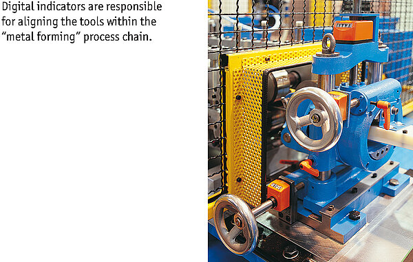
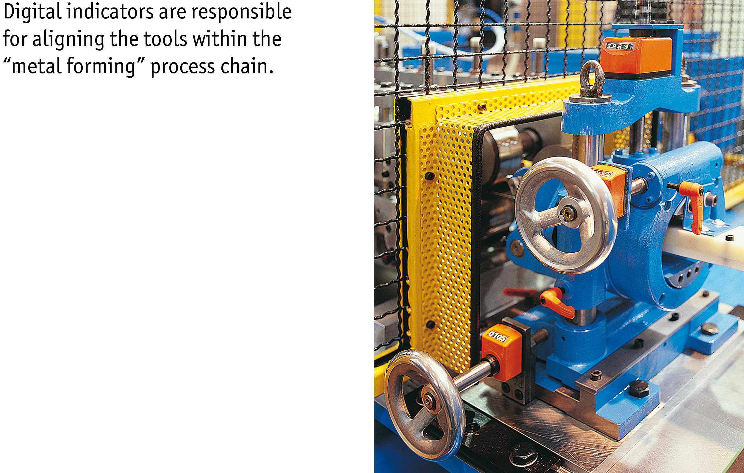
Batch sizes are becoming smaller and smaller down to the one piece in industrial production. The machines must be converted for each product change. This can be setup processes in which the equipment – for example, tools – is changed. Or a new dimension is set in the machine, usually by positioning axes or spindles to new target values. Positioning systems help to make precise adjustments every time a product is changed.
Position indicators show the operator and the controller when the correct position has been reached. Technically, the possibilities range from a cost-effective, purely mechanical system to Industry 4.0-capable components that can communicate with one another. Without an accurate positioning system, the process becomes more error-prone and the risk of rejects arises. Positioning drives are fully automated, without manual intervention.
In a machine, it must be possible to measure a current position, for example that of a threaded spindle, with a suitable measuring system with a defined accuracy. Therefore, a measuring system is located as a core element in each position indicator. It has a high accuracy, typically with a tolerance of approximately ± 0.5 degrees. In addition, a position indicator provides controllable digital display values. Different indicator values are possible depending on the corresponding spindle pitch. As a rule, the rotational movement of the spindle is converted into a linear movement, which a slide sets.
The spindle pitch indicates which path is carried out linearly per revolution. This is always dependent on the size of the spindle. Position indicators always operate according to an absolute measuring principle. This means: The indicator receives an absolute reference, and this position value is then stored permanently. Depending on the mode of operation, we speak of mechanical or electronic position indicators. The reference is provided via mounting in the case of mechanical position indicators and via a battery-buffered measuring system in the case of electronic displays.
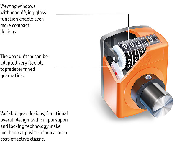
Robust and inexpensive: These points speak primarily for mechanical position indicators. A large number of transfer ratios are available for this purpose to be able to map specific applications. Mounting via a hollow shaft is crucial for easy and cost-effective retrofitting of the position indicators.
The special feature of the mechanical position indicators is that they are suitable exclusively for a specific application in each case, in other words, for an application with a specific spindle pitch. This is why a machine often has many different indicator variants.
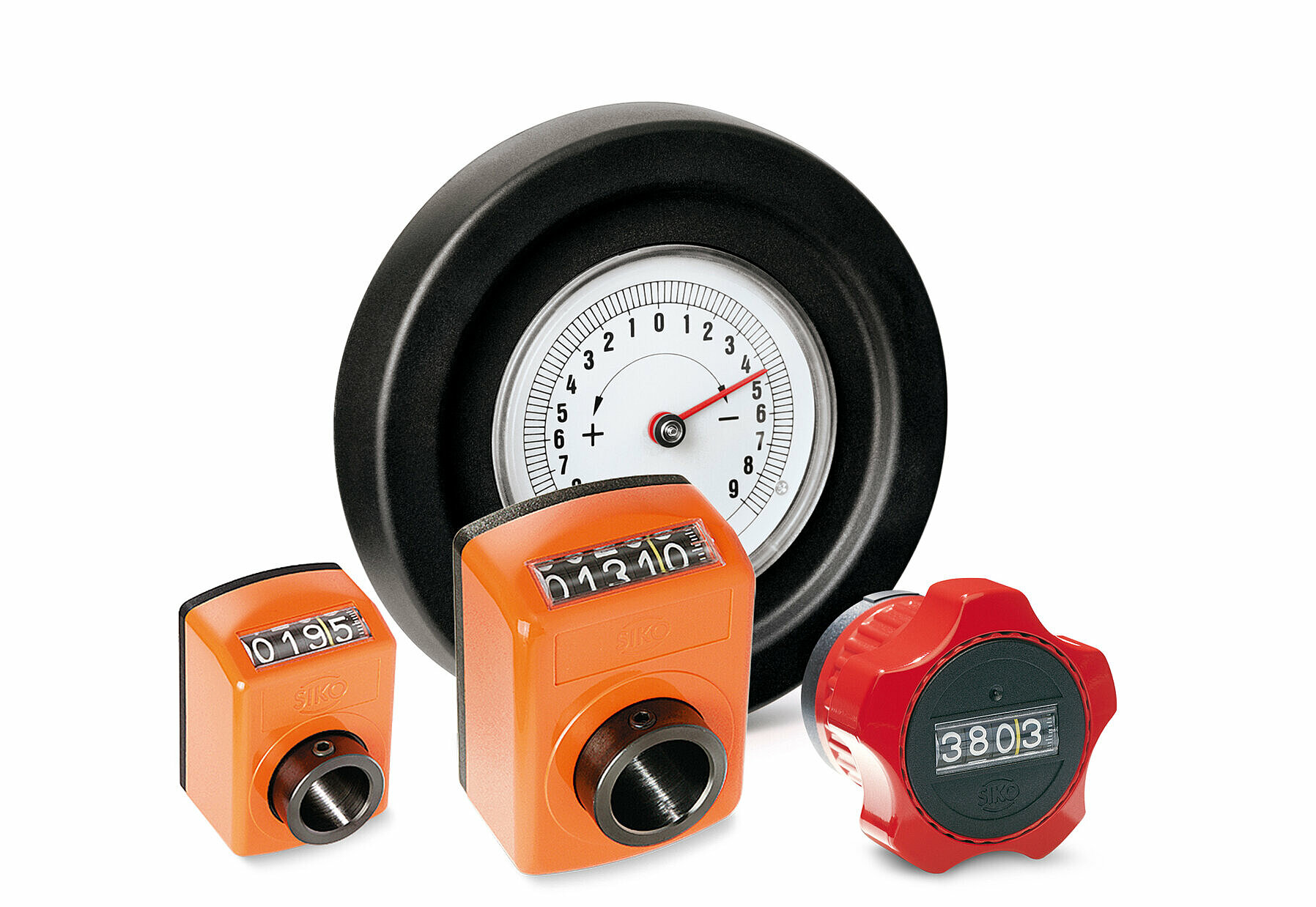
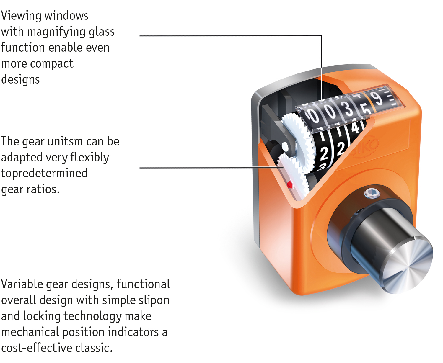
The application must be specified in advance, and the designer must define the requirements for the indicator in detail before a device can be delivered. The mechanical-digital position displays are a special design, also called SIKO counters or position indicators, which display the values in decimal places in powers of ten by means of numerical rolls. Therefore, the term “digital” is used, although it is not an electronic display. The position values can be recorded with high precision and are displayed in a clearly legible manner. The display value per revolution is appropriately designed via an integrated gear for the respectively required spindle pitch.
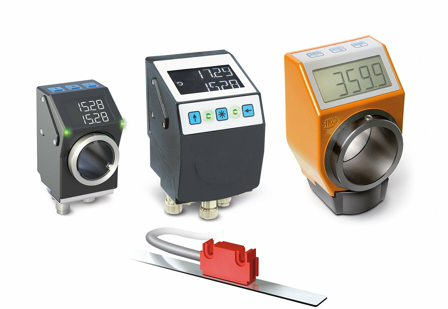
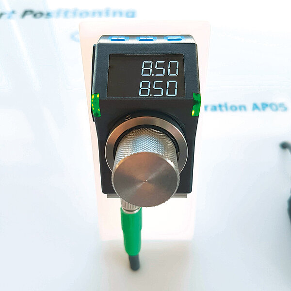
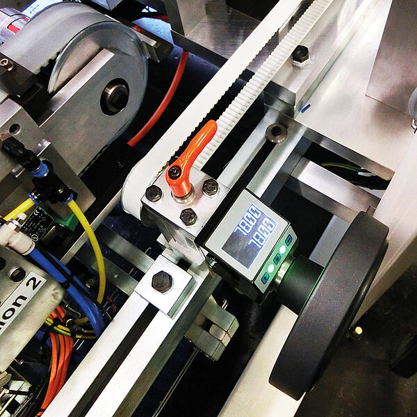
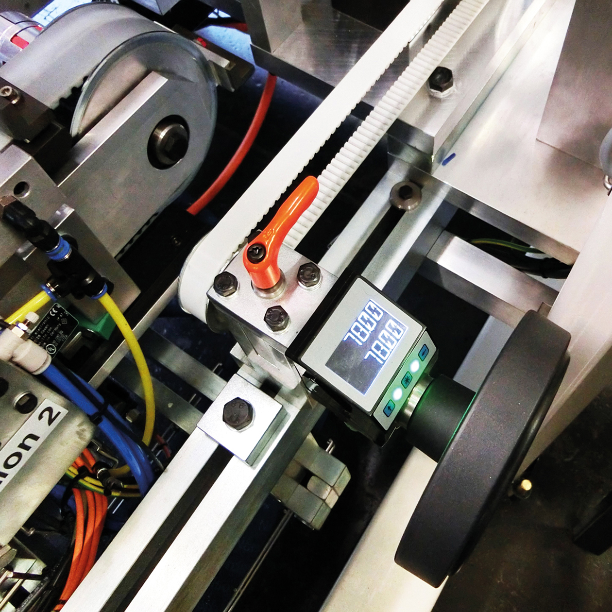
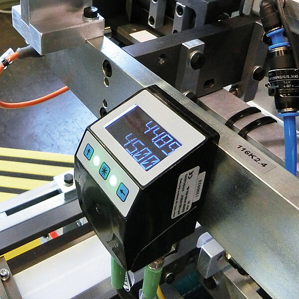
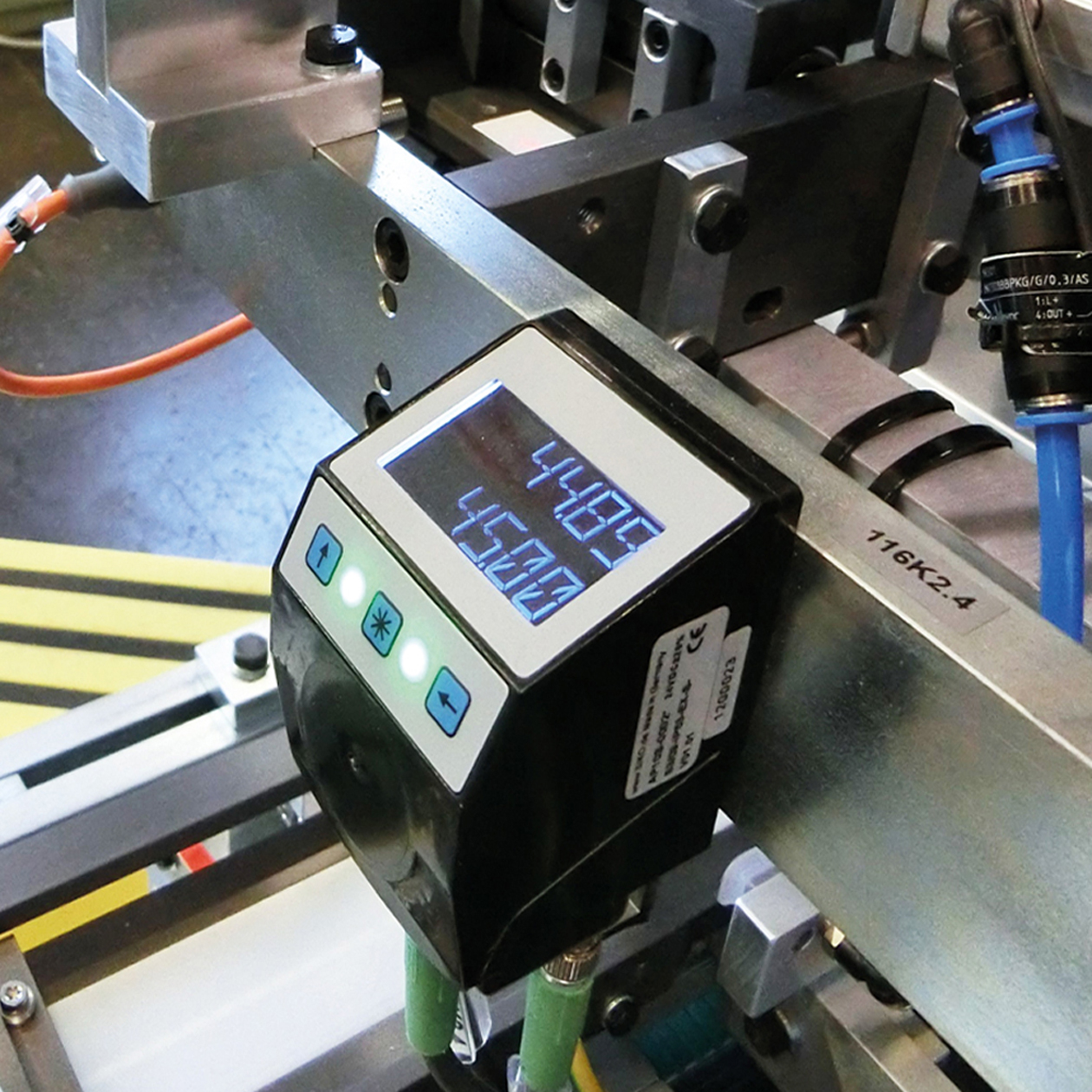
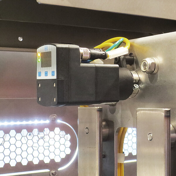
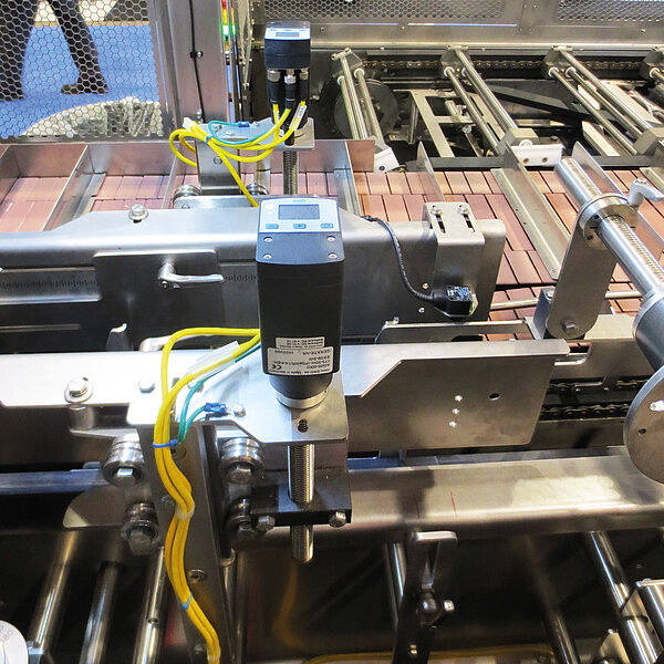
Electronic position indicators differ from mechanical ones at first glance by an LCD display. However, they offer decisive advantages. The most important: Electronic position indicators can be freely programmed. This makes it possible to use one model for different applications. It is possible to configure numerous parameters via the position indicators: spindle pitch, decimal places, direction of rotation, installation position or use in angle mode.
Thanks to the flexible programmable display values, electronic position displays can be used particularly well in the case of non-metric spindles, for example, inch spindles from the American region. The same applies to gear ratios, i.e., adjustments that are not attributable to integer spindle pitches. Free programmability is generally helpful in special-purpose machine manufacturing. Another advantage is the reliable measurement of the electronic position indicators thanks to the magnetic or capacitive measurement method
The axis motion is detected without contact. The magnetic measuring method is especially robust and insensitive to soiling or vibrations. Compared to the mechanical-digital position indicators, very high resolutions can be achieved with the electronic indicators – up to 3,600 counting steps per revolution
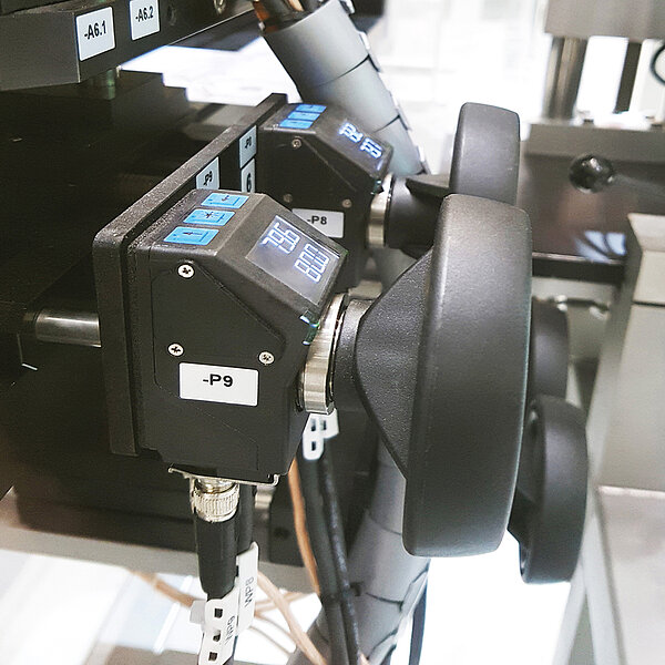
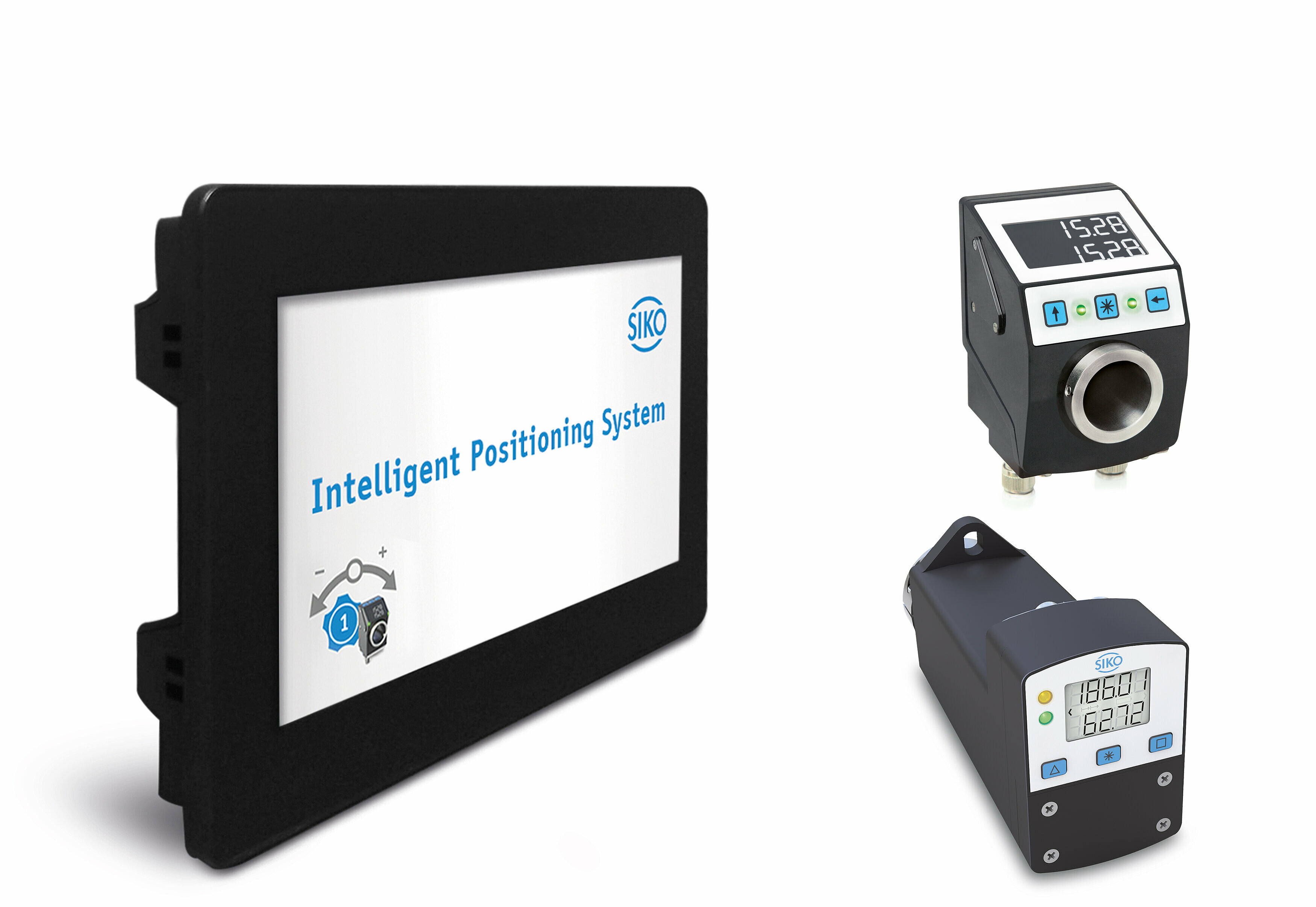
The electronic position indicators for monitored format adjustment go one step further. They additionally have a bus interface. In bus-controlled operation, setpoint values and actual values can be exchanged between the individual absolute position indicators and an upstream control unit. There are also position indicators, such as the SIKO AP10S, which are used for monitored slide adjustments. These intelligent positioning systems are used when positioning is to be carried out via slides or linear guides.
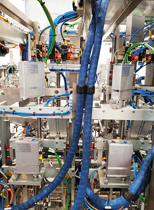
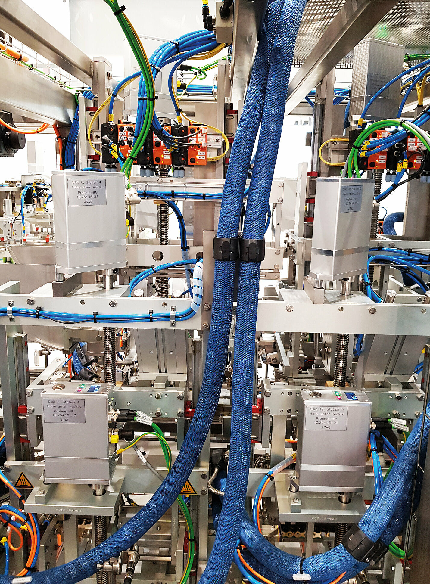
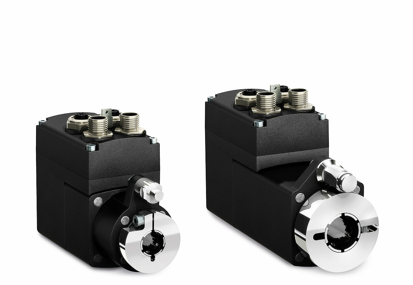
The next step is the complete automation of positioning via compact positioning drives. This exclusively concerns spindle adjustments, since an actuator is a purely rotary system. The basic idea of a spindle drive is its highly integrated design, via which “all” components are present in the device itself: a brushless DC motor, a low-play and high-performance gear, a position encoder as well as power and control electronics. As a result, the positioning drive, or also called actuating drive, can be connected directly to the control. The positioning drive is also easy to adapt to the existing spindle thanks to the integrated hollow shaft.
A special feature of these drives is their compact design, because the space in the machine units is often very limited. Standard interfaces enable direct communication with superordinate programmable logic controller (PLC). This functions as a control center, which specifies the setpoint values and also the start command to the drive. However, the control of the fully automated positioning takes place within the drive. The process data, i.e., position, speed, and direction of rotation, are then provided continuously and can also be read by the controller.
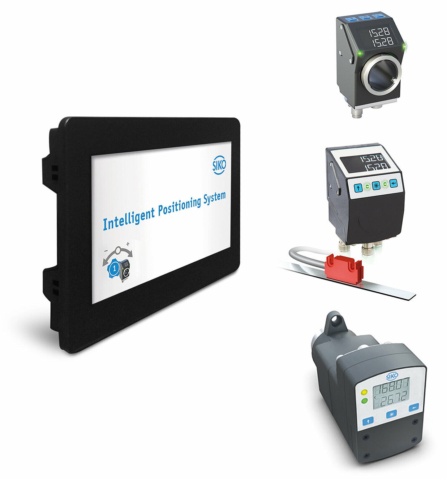
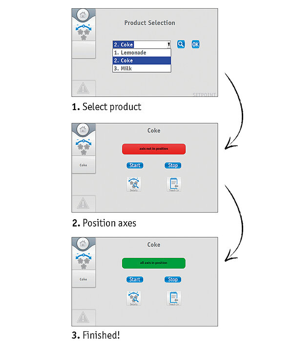
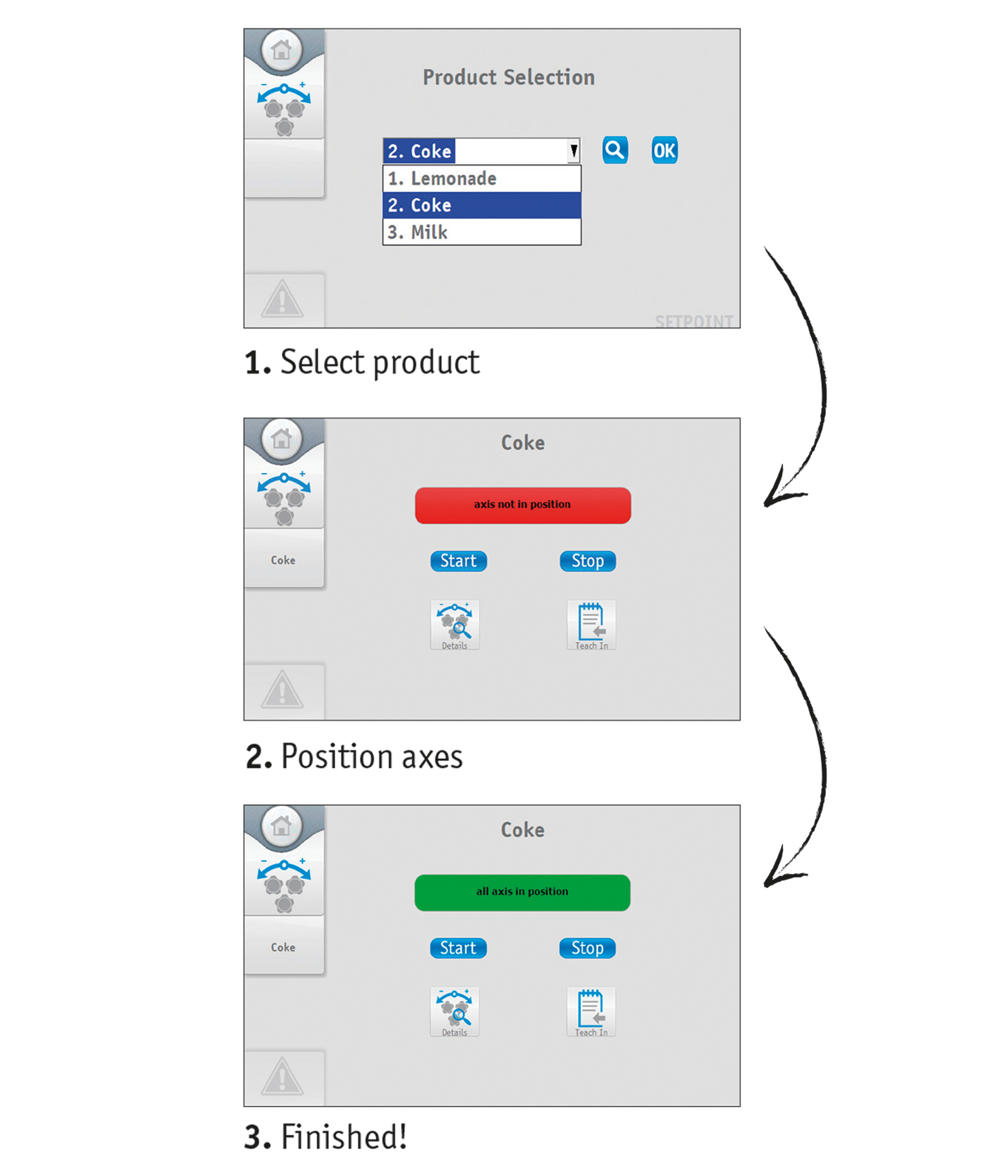
In older machines, there is partly no machine control or they only have a controller with outdated interfaces. If the system is to be optimized, operators usually look for a solution that promises simple electrical installation and commissioning and requires only slight programming knowledge. SIKO provides the IPS1010 HMI control IPS1010 (Intelligent Positioning System) for these cases. Everything is pre-programmed in the plug-and-play system. A cost-intensive conversion to a PLC is no longer necessary; the IPS1010 has a ready-to-use user interface. All SIKO devices in the area of intelligent format adjustment can be parameterized using a pre-installed program via the display, i.e., position indicators and/or positioning drives. The combination of these retrofit devices represents a retrofit system.
Consequently, a large number of formulas for various products can be specified during ongoing operation. Setpoint values are then automatically sent to all axes or linear adjustment positions, to which the positioning drive (actuator) can move automatically or even manually adjusted and monitored with an electronic position indicator. The degree of automation of the machine must be determined individually. The pre-programmed user interface still leaves room for setting up and programming individual settings.

