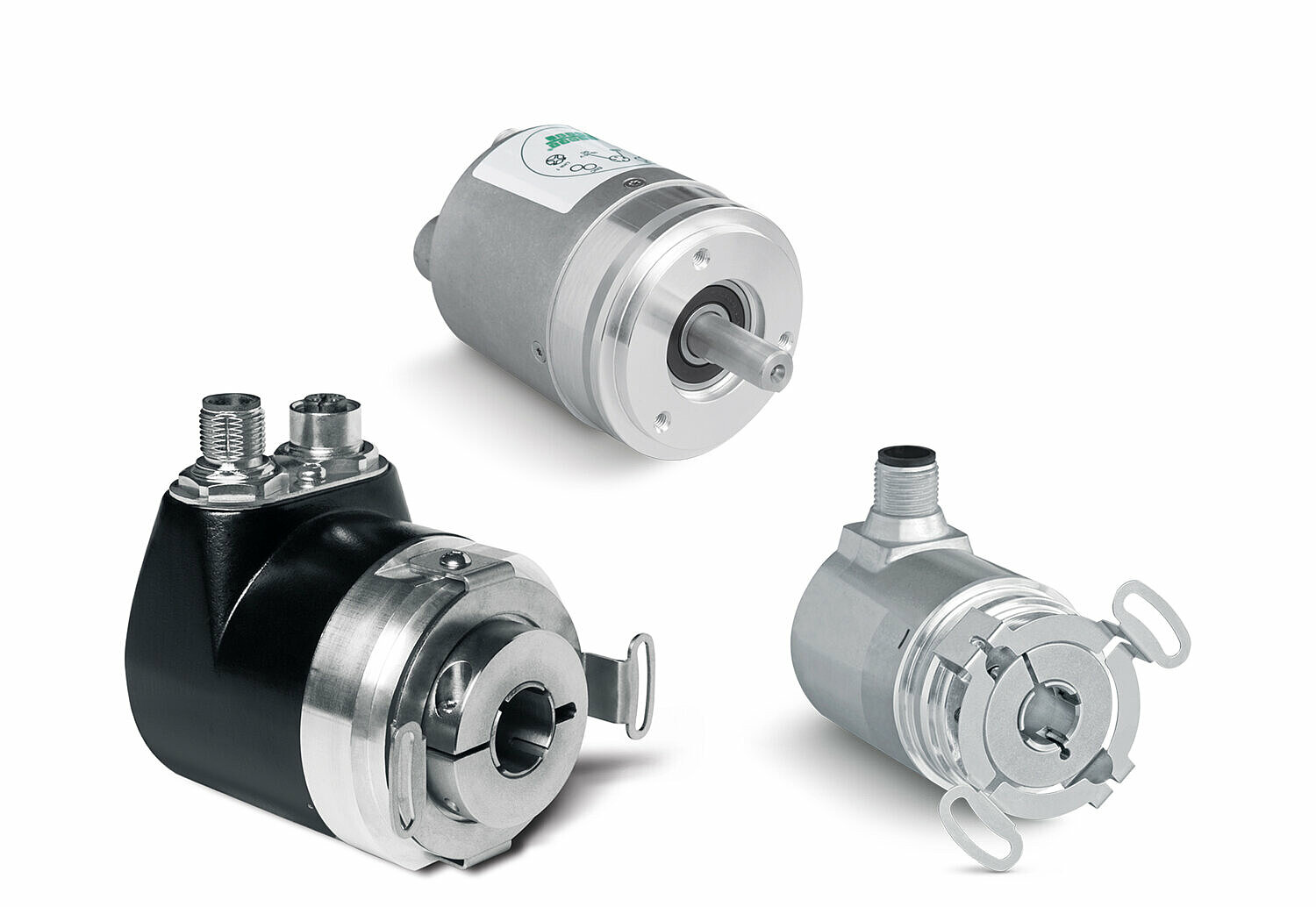
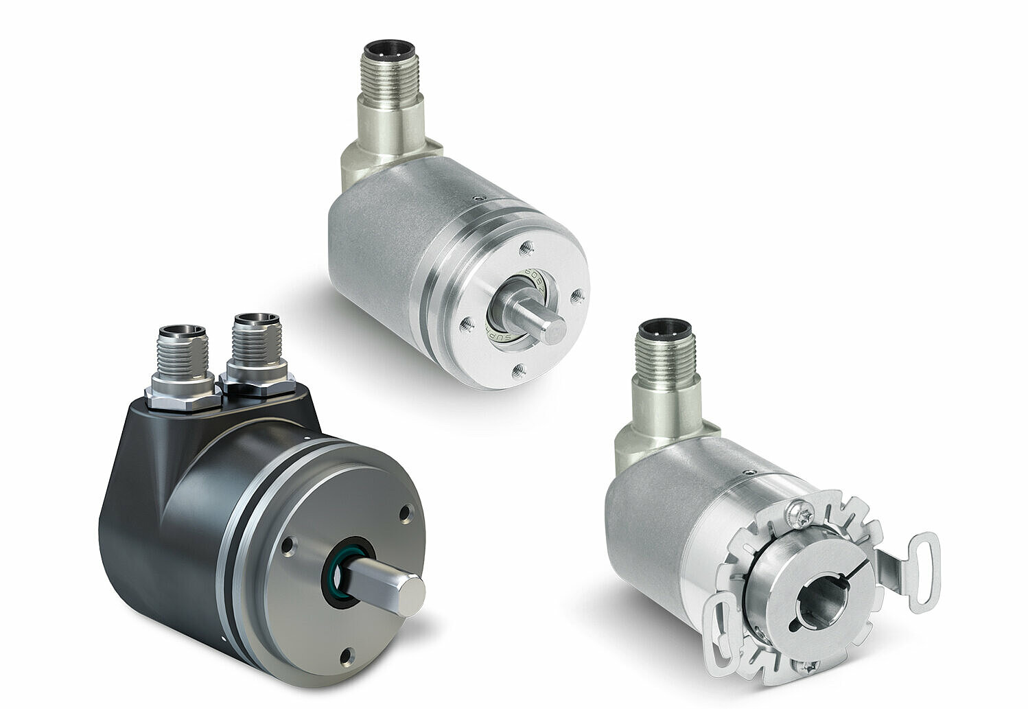
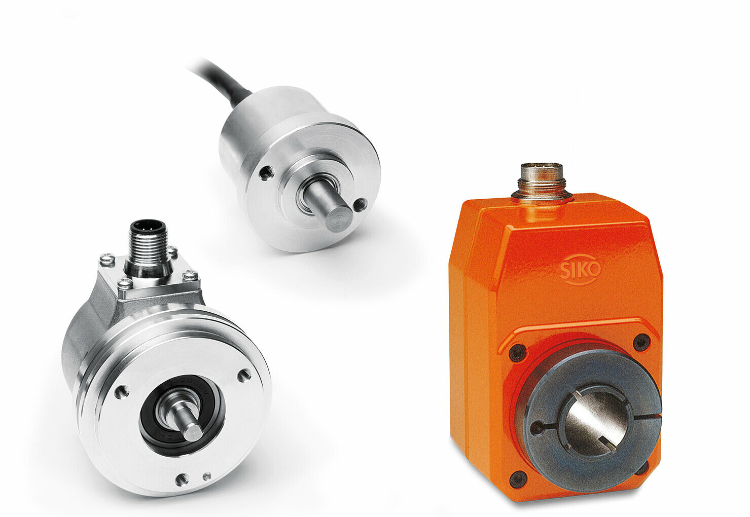
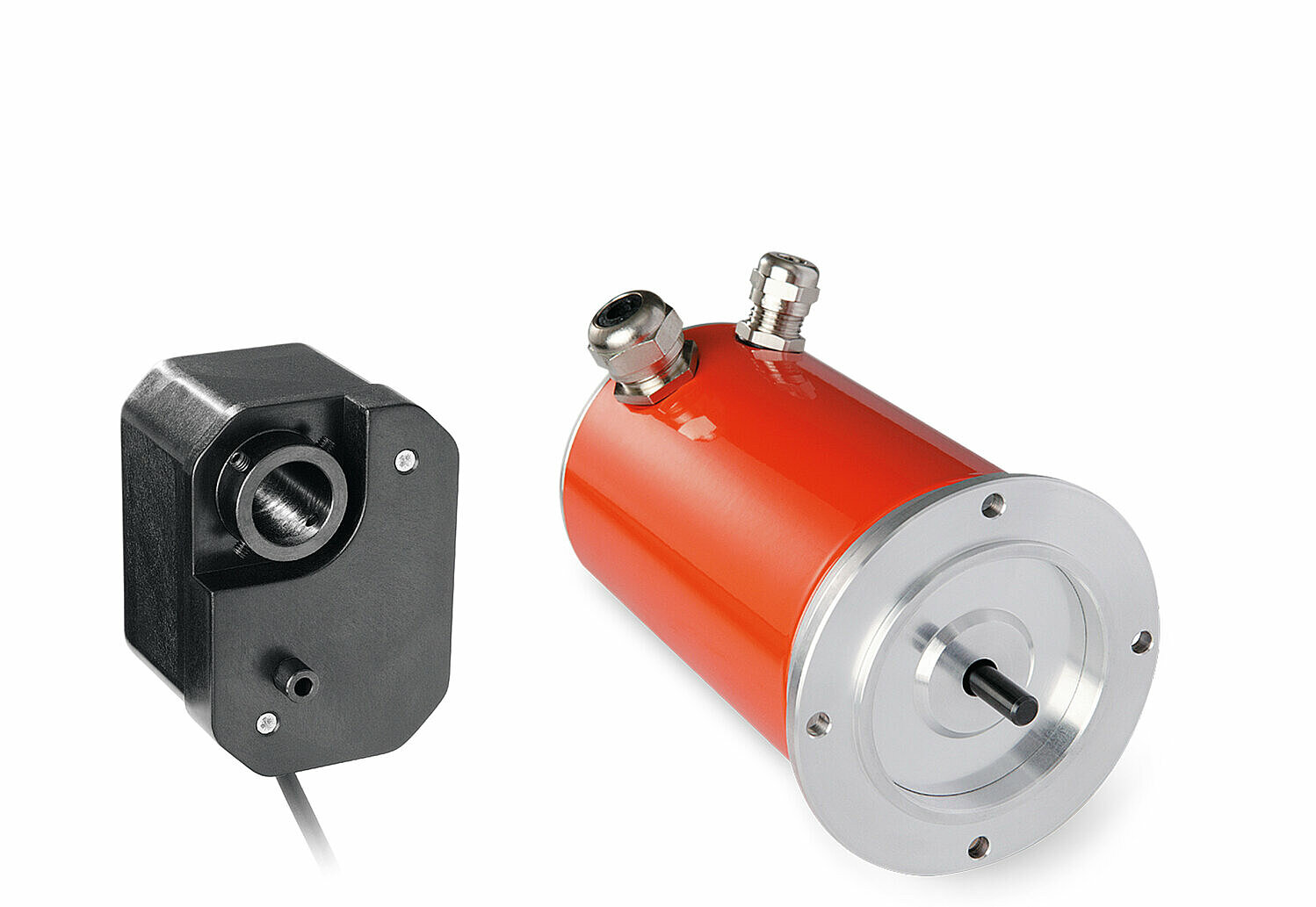
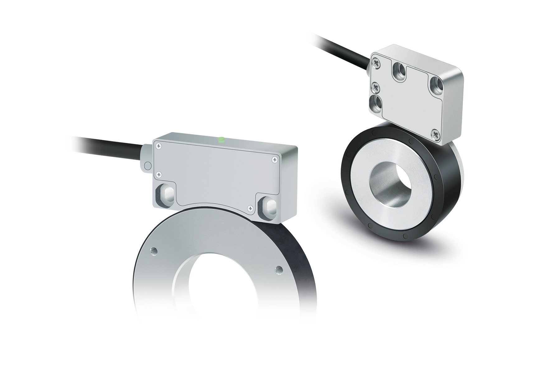
Rotary encoders, also called encoders, are position encoders (sensors) for linear or rotary motion. They primarily generate digital position and velocity signals. In most cases, the physical measuring principle is based on an optical, magnetic, inductive or capacitive method. Each physical measuring principle must be protected against external interference.
Shadowing, filtering, and shielding. In the past, magnetic encoders have been shown to work reliably even in adverse environmental conditions such as frost, dew, light, oil and water. External foreign fields are also permissible with suitable selection and arrangement of the magnetic sensor elements.
What kind of coding do rotary encoders have?
A simple coding (assignment) can be light/shadow or magnetic north/south pole, etc. A number of identical and/or different such codes form the scale. The sensor elements then convert these physical quantities into electrical signals. The output signals are generated in the measuring electronics (sensor elements and other wiring).
What types of rotary encoders are there when determining a position?
A further distinction is the type of rotary encoder: incremental or absolute.
Incremental: from Latin = counting. The tracking or evaluation electronics detect counting pulses for determining the position. Therefore, a currentless adjustment cannot be detected system-dependent. The scale usually consists of a periodically recurring division.
Absolute: the position value is available at any time (even immediately after switching on without movement). Each position is clearly and uniquely coded on the scale.
Which output signals are possible and how can the measuring range be extended to several revolutions?
Output signals: 2 square-wave signals (quadrature signals) offset by 90° are frequently used for incremental encoders. The levels are often based on RS232, TTL or HTL (push-pull). These signals are often generated differentially for better transmission reliability. As an alternative, differential sine/cosine signals are provided. They provide the advantage of enabling a higher resolution at a simultaneously low transmission frequency by calculating intermediate values (interpolation). An additional reference signal is recorded and output to detect an unambiguous position for incremental rotary encoders.
Absolute rotary encoders: As a rule, an intelligence (μC, ASIC) is already present in the rotary encoder as a result of the evaluation of the individual signals. This enables different transmission protocols.
Examples:
- Ethernet-based fieldbuses: Profinet, PowerLink, EtherCAT, EtherNet/IP, etc.
- Profibus
- CANopen, CANopen Safety, SAEJ1939
- SSI, BISS
- Among others
Multi-turn absolute rotary encoder: The scale attached to the encoder shaft together with the measuring electronics represents a unique position within one revolution. However, the position value is then repeated with each revolution. The unique measuring range covers 360° mechanically. This is called a "single-turn encoder". If you extend this by a function block, which records the revolutions, you get a "multi-turn encoder".
There are basically three options available for implementing such a “multi-turn function”:
- Additional sensors and mechanics are fitted with a gearbox to enable detection of up to 65536 revolutions
- A battery enables permanent operation of a revolution counter
- An "energy harvest module" enables the detection of a counting pulse, the operation of an up-down counter and the non-volatile storage of the position value. Energy harvesting collects energy from the environment (vibration, temperature difference, pressure, movement). A well-known representative is the Wiegand sensor
EN ISO 13849 and/or IEC 61508 standards are used to integrate additional safety functions. Functional safety: The encoders have a central function in a machine. A failure or a faulty position value can have fatal consequences, particularly in the case of automated axes. For this reason, the demands on the encoder are very high. Availability, the ability to detect errors, and secure transmission require additional measures. One example is a redundant sensor system.
Depending on the application, key figures such as performance level (PL) or SIL level together with other key figures (MTBF, DC, Pfh, etc.) are a measure of the encoder’s ability to function safely and reliably. The secure transmission of position and speed values is ensured, among other things, by special protocols, e.g., CANopen-safety. SIKO rotary encoders are often used in industry and mechanical engineering. SIKO specializes in the development of special rotary encoders and sensor solutions for use in mobile automation.

